 | In this issue: | • | Application Brief
Two new circuit breaker designs provide protection from accidental switching | • | Application Brief
Automatic charging relay—an alternative to multiple output charging systems | | • | Application Brief
Using Blue Sea Systems’ battery switch AFD terminals to indicate switch position
|
| NEWS
Blue Sea Systems 2007 catalog will be in the hands of its distributors by August 4, 2006.
Blue Sea Systems launches its new website in September 2006.
EVENTS
MAATS 2006 Show
July 19-21
Las Vegas, NV, USA

Make your travel plans for MAATS (Marine Aftermarket Accessories Trade Show). It will be at Caesar's Palace in Las Vegas, July 19-21. Look for the Blue Sea Systems booth 643. Click here for information about MAATS 2006.
Blue Sea Systems Circuit Solutions™ newsletter archives

Issue 26
(May 23, 2006)
Press Release:
Blue Sea Systems' new L-Series solenoidApplication Brief:
Three practical applications for the CL-Series BatteryLink™ ACR: Load shedding, pilot house navigation battery isolation, charge current limiting Technical Brief:
Choosing circuit protection
Update:
Blue Sea Systems’ engineering contributes to ABYC standards revisions

Issue 25
(April 17, 2006)
Press Release:
300A ANL and SEA Fuse Blocks Application Brief:
600 ampere BusBar negative tie point Application Brief:
Supplying power to large loads
Issue 24
(March 22, 2006)
Press Release:
150A BusBar Application Brief:
Improvements to 150A BusBars

Issue 23
(February 15, 2006)
Press Release:
WeatherDeck™ Water Resistant Circuit Breaker Panels Technical Brief:
IP (Ingress Protection) ratings Application Brief:
WeatherDeck™ Water Resistant Circuit Breaker Panels Technical Brief:
Common switching applications
Issue 22
(March 22, 2006)
Press Release:
Blue Sea Systems' m-Series (Mini) Battery Switch Application Brief:
m-Series Battery Switch Technical Brief:
UL Marine Listed, battery switch testing
For a complete list of past Circuit Solutions™ issues, click here.
|
| Application Brief
- Improving marine electrical systems with Blue Sea Systems products
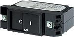
Two new circuit breaker designs provide protection from accidental switching
Toggle actuated circuit breakers and raised rocker circuit breakers can be accidentally tripped. This may be just a nuisance in some situations, but an accidental trip can have serious consequences in other situations, such as when the circuit breaker is in a 24-hour circuit for a bilge pump.
One approach to this situation is two new modern flat actuator designs, one with a built-in reset slot, that are resistant to accidental switching. These circuit breakers are available in two sizes—C-Series 2.5” large case, and A-Series 2” small case. Flat actuators are flush in the ON position, eliminating risk of accidental switching. The color actuator indicates the OFF position. The Slot Reset circuit breaker can only be turned off by inserting a small screw driver into the slot.
Flat | | 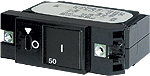
Slot Reset |
These circuit breakers are magnetic-hydraulic. Their trip free design cannot be held ON during a fault condition. They are marked with International ON/OFF symbols which makes them easy to mount vertically or horizontally. Both the C-Series and A-Series breakers from 5A to 250A fit the same panel aperture, the same aperture as the common Raised Rocker. They are CE marked.
C-Series large case 2 ½”, available in flat rocker.
• Single, double and triple pole
• 60-250A
• 2,000 – 10,000A AIC
• Up to 80V DC
• Single pole 60, 80, 100A
• Double pole 150, 200A
• Triple pole 250A
• Terminal studs are 1/4” – 20 x 0.545” SS
A-Series small case 2”, available in flat and slot-reset rocker.
• Single pole
• 5-50A
• 2,000-7,500A AIC
• Up to 80V DC
• Up to 250V AC
Terminal studs are #10 – 32 x 0.3125” SS
Application Brief
- Improving marine electrical systems with Blue Sea Systems products
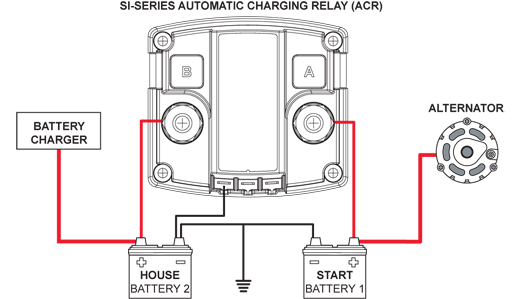
Automatic charging relay—an alternative to multiple output charging systems
What do you do when the number of battery banks on your boat is greater than the number of charging outputs from your system’s battery charger, and you want to provide a charge to all batteries? How do you design a boat electrical system that charges two battery banks without adding the cost of a dual output charger? Instead of upgrading your charging system, or installing a system with multiple outputs, install an automatic charging relay (ACR). The cost of a charging system with multiple outputs is considerably more expensive than one with single output, making the installation of the ACR a less expensive option.
For example, consider a typical marine electrical system with two battery banks, a battery charger with one output, and an alternator. To charge both battery banks from your single output charger, connect the ACR between the battery banks. Connect the alternator to charge battery 1 (start battery), and connect the charger to charge battery 2 (house battery). When the charger is charging battery 2, the ACR will combine battery 2 and battery 1 for charging. When the alternator is charging battery 1, the ACR will connect battery 1 and battery 2, and both batteries will be charged. With the installation of the ACR, when at dock and plugged into shore power, the charger is supplying a charge to both battery banks; when the engine is running, the alternator is charging both battery banks.
Similarly, if you are adding an auxiliary battery to power a windlass, you can connect the auxiliary battery through an ACR to a battery bank that is attached to a charger. In this way, you are able to charge an additional battery bank without upgrading the charger to one with multiple outputs.
Blue Sea Systems provides three ACR options with 60A, 120A, and 450A continuous current ratings:| • | CL-Series BatteryLink™ ACR (PN 7600) with a current rating of 60A, can be connected to sense one or two charging sources. By connecting a jumper wire between terminal 1 and B, the ACR will sense both batteries. | | • | SI-Series ACR (PN 110070011, 110070021) with a current rating of 120A (available in September 2006), automatically senses two charging sources | | • | L-Series ACR (PN 9112) with a current rating of 450A, can be connected to sense one or two charging sources. |
Each ACR automatically connects batteries during the charging cycle and disconnects them under discharge.
When combined with Blue Sea Systems’ Dual Circuit Plus™ Battery Switch (PN 5511e or 6011), all three ACR models fully automate the charging of two batteries. The combination of the Dual Circuit Plus™ Battery Switch and ACR provides a practical and less expensive solution to manage:| • | Isolated battery circuits | | • | Emergency parallel backup operation | | • | Automated charge management |
Simply turn the battery switch to the ON position when arriving on the boat, and turn it to the OFF position when leaving. You no longer have to worry about which batteries are charging or discharging.
Before replacing your charger or inverter/charger, consider the benefits of an ACR; and for a fully automatic system, add a Dual Circuit Plus™ Battery Switch.
Application Brief
- Improving marine electrical systems with Blue Sea Systems products
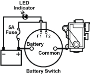
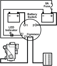
Using Blue Sea Systems’ battery switch AFD terminals to indicate switch position
Alternator Field Disconnect (AFD) is a feature of some battery switches—for example, Blue Sea Systems’ e-Series ON/OFF (PN 9004), HD-Series ON/OFF (PN 3001), e-Series Selector (PN 9002), and HD-Series Selector (PN 3003). AFD protects the diodes in the alternator if the battery switch is switched to the OFF position while the engine is running.
When not used to protect the diodes in the alternator, the AFD connections can be used to indicate when the battery switch is in any position but OFF—ON for the ON / OFF; 1, 2, BOTH for the Selector. The AFD switch is closed whenever the main contacts of the battery switch are in any ON position. Various indicators can be connected to the AFD terminals, such as lights, bells, or sound systems which will be activated only when the cross-connect switch is ON. This can be crucial if the battery switch is located in a remote location or otherwise not visible.
The AFD switch circuit should be limited to a load of 5A or less. Directions:| 1. | Connect the anode side (+) of the LED to the AFD terminal (F1). | | 2. | Connect the cathode side (-) of the LED to the system negative. | | 3. | Connect the battery positive to the AFD terminal (F2). |
 |  | | ON/OFF | Selector |
|
| |
You are receiving this newsletter from Blue Sea Systems because you have contacted us or subscribed on our website.
If you wish to unsubscribe, please send an E-mail to [email protected] with the word REMOVE as the subject.
If you’ve received this newsletter from a third party and you wish to subscribe to Blue Sea Systems' eNewsletter, please send an E-mail to [email protected] with the word SUBSCRIBE as the subject.
Blue Sea Systems would like to hear from you regarding any questions you may have, or any suggestions for publication in future editions of the Circuit Solutions™ Newsletter. Please send us your suggestions to: [email protected].
Copyright ©2006 - Blue Sea Systems, Inc.
425 Sequoia Drive, Bellingham, WA 98226 USA
Phone: 360-738-8230
Fax: 360-734-4195
Website: www.bluesea.com |
|
|